GC-Prevue is my favorite Gerber Viewer.
To
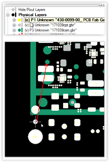
align layers select a pad or feature that exists on
both layers. Select all objects on the
layer that is to be moved. Place the cursor near a pad, press S (select) key to
center on the pad then press
the Z (zero) key. Press space bar to
move (unlock) crosshair. On the other
layer place the cursor near
the same pad, select
S key, then O (offset) key, then OK
to align the layers.
select edit mode (press e key) for the layer the is to be move
Thats it !
Get trace resistance from Saturn PCB Calculator - Conductor Properties
Calculate Trace Voltage Drop using Ohms Law
That's it !
Altera AppNote AN672 was recently updated. This app note is perfect for anyone who is on the high speed learning curve.
'via Blog this'
How to 'Exclude' parts in HyperLynx | Mentor Graphics Communities:
An unanswered question.
There are resistors in this design that can be fitted or not fitted to determine the signal paths.
To accurately simulate this design Hyperlynx would need to analyze the signal path and stub lengths based on which parts are installed and not fitted.
click on image to view
The question is how would you remove the stubs and paths from within Hyperlynx to simulate the design as though the parts were not fitted (removing the stub paths).
Comments welcome and appreciated !


