

Thursday, September 11, 2014


Friday, September 5, 2014
PCBDESIGN007 Isola's I-Speed Endorsed as Laminate Choice for PCBs
"I-Speed has been endorsed by two leading companies as the laminate of choice for PCBs using sequential lamination technology, requiring high conductive anodic filament (CAF) reliability and improved, cost effective signal integrity."
Source:
PCBDESIGN007 Isola's I-Speed Endorsed as Laminate Choice for PCBs:
'via Blog this'
Source:
PCBDESIGN007 Isola's I-Speed Endorsed as Laminate Choice for PCBs:
'via Blog this'
CTE-Z - RoHs Thermal Stresses on VIAs
How To PCB - Thermal: Jack Olsen
Jack has an excellent description about CTE-Z and the thermal stresses RoHs reflow has on vias.
Visit Jack Olsen's site 'How to PCB' to see the full article.
Click here to view the thermal stress animation.

The Z axis stresses can cause vias and traces to fracture.

See the link above to visit Jack's site and read the article.
Jack has an excellent description about CTE-Z and the thermal stresses RoHs reflow has on vias.
Visit Jack Olsen's site 'How to PCB' to see the full article.
Click here to view the thermal stress animation.
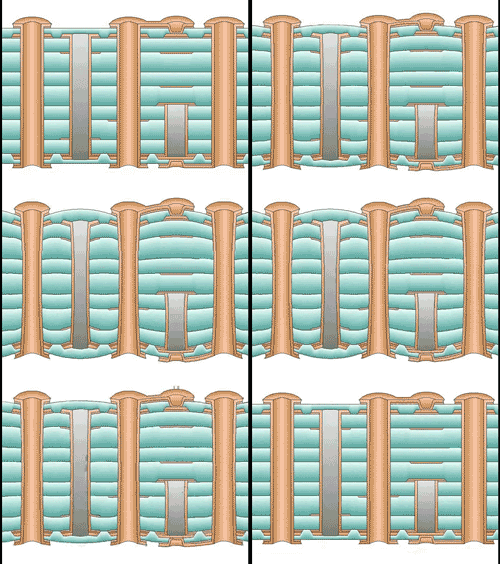
The Z axis stresses can cause vias and traces to fracture.
See the link above to visit Jack's site and read the article.
Hipot Testing Articles
Best Methods for Safe Hipot Testing - Slaughter
Understanding HiPot Certification Testing - Electronic Design
'via Blog this'
Understanding HiPot Certification Testing - Electronic Design
'via Blog this'
Monday, September 1, 2014
Differential Pair Routing
"This application note discusses the selection and optimal settings of differential pair design rules. When it comes to successfully deploying differential signals in high-speed designs, symmetry is the key."
Barry sums it up nicely.
"In Conclusion
1. Symmetry is the key to successfully deploying differential signals in high-speed designs. Maintaining the equal and opposite amplitude and timing relationship is the principal concept when using differential pairs.
2. Match the length of each signal of the pair. This ensures that there is no skew between the signals of the pair and flight times will be identical.
3. Route the differential pairs to impedance and at the optimal spacing: Gap = 2 x trace width.
4. To control crosstalk, keep aggressors far away from differential pairs, especially on
Microstrip (outer layers). A good rule of thumb here is Gap = 3 x trace width. PCB"
'via Blog this'
Subscribe to:
Posts (Atom)