Panasonic Develops Mass Production Technology for ALIVH-F Resin Circuit Board Using Polyimide Film
Thursday, June 27, 2024
Tuesday, June 4, 2024
Microvia Copper Fill Process
Microvia copper fill is a technique used in high-density interconnect (HDI) PCBs to create reliable electrical connections between different layers. Here's a breakdown of the process:
Why copper fill?
- Improved Conductivity: Solid copper offers superior conductivity compared to alternative via plugging materials like epoxy resins. This translates to better signal transmission.
- Higher Reliability: Copper filled vias are less prone to cracking or delamination during thermal stress, enhancing the overall reliability of the PCB.
- Manufacturing Efficiency: Copper plating is a well-established process in PCB fabrication, allowing for efficient integration into the existing workflow.
The Copper Filling Process:
- Preparation: The drilled microvias are cleaned and prepared for electroplating to ensure proper adhesion of the copper.
- Electroplating: The PCB panel is placed in a plating tank containing a copper sulfate solution. An electric current is applied, causing copper ions to be deposited on the via walls and gradually fill the microvia.
- Additives and Techniques: Special additives might be used in the solution to achieve conformal plating, ensuring complete filling and minimizing voids within the via. Techniques like horizontal or vertical plating equipment may be used depending on the via aspect ratio.
- Resin Filling (Optional): After copper plating, some manufacturers might fill any remaining voids with conductive or non-conductive epoxy resin for additional stability.
- Planarization: The PCB surface is polished to ensure a smooth and even finish.
Advantages of Copper Filled Microvias:
- Increased packing density of electrical connections in the PCB.
- Improved signal integrity due to superior conductivity.
- Enhanced reliability through robust via connections.
- Compatibility with existing PCB fabrication techniques.
Things to Consider:
- Copper filling process adds complexity to PCB manufacturing, potentially affecting cost.
- Microvia dimensions play a crucial role in achieving complete and void-free copper filling.
If you're designing HDI PCBs and require high-density, reliable connections, copper filled microvias are a strong option. However, discussing the design and feasibility with your PCB manufacturer is recommended.
Saturday, May 25, 2024
Tuesday, May 7, 2024
PCB Stackup Designer - Sierra Circuits
Sierra Circuits - Online Stackup Designer
Stackup Designer | Sierra Circuits
Bandwidth, Rise time & Critical Length Calculator | Sierra Circuits
Sunday, May 5, 2024
Footprints - Common Mistakes
Problem - Paste Stencils should NOT have inside corners

Solution - All openings in the paste stencil must have outside corners.

Problem - Silkscreen lines along sides of chip Resistors, Capacitors and Inductors will interfere with aqueous cleaning processes.

Solution - Remove silkscreen as shown below to allow aqueous cleaning processes to remove flux residues under chip Resistors, Capacitors and Inductors.
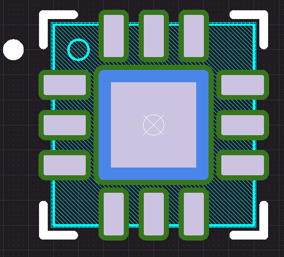
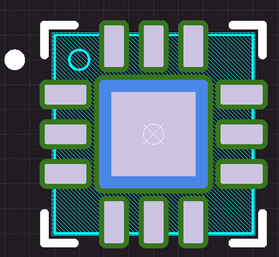
Problem - Silkscreen under or too close to the edge of Bottom Terminal Components.

Why ? Silkscreen registration accuracy is typically plus or minis 5mils.
Analogy:
Think about speed bumps or undulations in a parking lot or in roads near schools.
Silkscreen will be the tallest feature on the outer layers of the PCB.
These raised silkscreen lines under or near the edge of the component can cause soldering yield problems especally for small fine pitched Bottom Terminal Components (BTC).
Solution - Keep silkscreen lines 5mils away from the edges of all Bottom Terminated Components, ie, QFNs and DFNs,
Problem - Excess solder paste on BTC pads.

Why ? Excess solder will form a raised pillow and the part will teeter totter during reflow.
The part can end up having shorted pads (solder bridges) on one side or open connections.
Solution - Reduce solder paste volume, to 50% to 60% of the pad's area.
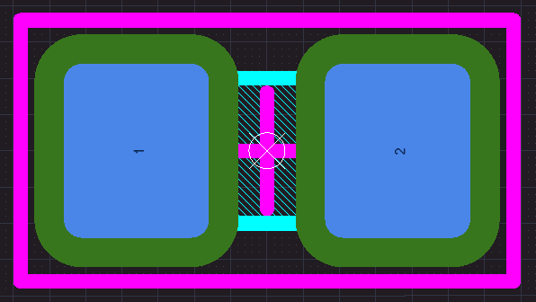
Example - Tiny QFN
Example - Small DFN

Example - Small QFN with Windowed Paste

Problem - LEDs and Diodes - Pin1 should be the Cathode (K)
Example - Wrong ! Pin 2 was assigned to the Cathode.

Example - Kingbright P/N APTD1608CGCK
Note Cathode (K) is Pin 1 and Anode (A) is Pin 2

Solution - The Cathode should be assigned to Pin 1.
That's it !
Saturday, April 27, 2024
High-Speed Interface Layout Guidelines - TI
High-Speed Interface Layout Guidelines (Rev. J) - Texas Instruments
Per Gemini - Google AI
There are actually two main reasons why differential signals are not always preferred for routing on the outer layers of a printed circuit board (PCB), and it has to do with the type of transmission line formed:
Microstrip vs. Stripline:
Outer layers create microstrip transmission lines, where the signal trace has a reference plane on one side (usually a power plane) and air on the other.
Differential signals rely on a consistent and symmetrical environment for optimal performance. Microstrip, due to its air exposure, introduces an asymmetry that can affect the common-mode vs. differential-mode propagation characteristics.
Controlled Impedance:
Precise control over the impedance of the transmission line is crucial for high-speed differential signals. Microstrip's impedance is more sensitive to variations in manufacturing tolerances compared to stripline.
However, there are some advantages to routing differential signals on outer layers:
Slightly Faster Signal Propagation:
Outer layers have a lower effective dielectric constant due to the presence of air. This can lead to marginally faster signal travel compared to inner layer routing.
Easier Access for Controlled-Impedance Routing Techniques:
The outer layers are more accessible for adding solder masks or prepreg layers to adjust the trace width and spacing, allowing for finer control over impedance.
In conclusion, the decision to route differential signals on outer layers depends on the specific application's priorities. For high-performance applications where signal integrity is paramount, stripline routing on inner layers with a controlled and symmetrical environment is usually preferred. However, for lower-speed applications where manufacturability and ease of access are important, outer layer routing with microstrip can be a viable option, considering the trade-offs mentioned above.
That's it !
Wednesday, April 24, 2024
Sunday, April 21, 2024
Microwave and RF Absorbing Materials
ARC Technologies, a Hexcel Company, is the leading supplier of microwave and RF absorbing materials for commercial and defense applications.
RF Interference Control | Hexcel
Wave-X™ Near Field Absorbers | Hexcel
RF Interference Control | Hexcel
Notes:
Aluminum doesn't block magnetic waves. Magnetic waves and electromagnetic waves, though related, are different. Aluminum is effective at blocking electromagnetic waves, especially at higher frequencies like radio and light waves. This is why aluminum foil is sometimes used to block radio signals.
For magnetic waves, however, aluminum acts like air because magnetic permeability of aluminum is very close to that of air. This means magnetic waves pass through aluminum just as easily as they pass through air.
If you need to block magnetic fields, you should use materials called ferromagnetic materials like steel or iron. These materials have a much higher magnetic permeability than air or aluminum, and they can significantly weaken magnetic fields.
That's it !
Hook-Up Wire

Remington - https://www.remingtonindustries.com/hook-up-wire/
DigiKey - 30STRPTFEKIT Remington Industries | Kits | DigiKey Marketplace
Sunday, April 7, 2024
USB 2.0 Physical Layer Testing and Debugging
This App Note describes the Bandwidth Requirements of an Oscilloscope and Probes.
Understanding and Performing USB 2.0Physical Layer Testing and Debugging

Source Tektronix
Tuesday, April 2, 2024
Gemini - USB Diff Pairs
Source Google Gemini
USB Differential Pair Length Matching
In USB design, differential pair length matching is crucial for maintaining signal integrity. Here's a breakdown of what it is and why it matters:
Differential Pairs in USB:
- USB uses differential signaling where data is transmitted on two balanced lines (D+ and D-).
- The difference in voltage between these lines carries the signal, making it less susceptible to noise.
Importance of Length Matching:
- Ideally, both lines in a differential pair should be exactly the same length.
- Any mismatch in length creates skew, which is the time difference between the arrival of signals on the two lines.
- Excessive skew can degrade signal integrity, leading to errors or data corruption.
Length Matching Requirements:
- The allowed skew varies depending on the USB version:
- USB 2.0 High-Speed: Maximum skew of 100 ps (picoseconds). This translates to a length difference of roughly 0.6 inches (15 mm).
- SuperSpeed USB 3.0 and above: Even tighter tolerances, with a maximum skew in the range of 30-60 ps. This translates to a much smaller length mismatch allowed, typically around 5 mils (0.13 mm).
General Guidelines:
- Keep the differential pair as close together as possible throughout their routing.
- Use design tools with differential pair routing features to ensure matching.
- If possible, keep the total length of the pair short, especially for USB 3.0 and above.
Additional Considerations:
- The length matching requirement applies to the entire signal path, including the PCB traces and any cables attached.
- While length matching is important, maintaining the correct differential impedance (typically around 90 Ohms for USB) is equally crucial.
By following these guidelines for differential pair length matching, you can ensure reliable signal transmission in your USB designs.
That's it !
Thursday, February 29, 2024
Thursday, February 22, 2024
Electronic Coatings
Electronic Coating Technologies | Homepage
Parylene Coating Services | Electronic Coatings Technologies
Parylene Conformal Coating Services | Specialty Coating Systems
Properties of Parylene Coating
- Ultra-thin, uniform films
- Chemical and moisture barriers
- Excellent electrical properties
- Superior thermal stability
- Biocompatibility
- Dry film lubricity
- Halogen-free variants
Sunday, February 18, 2024
Subscribe to:
Posts (Atom)