When a design requires equal-length traces between the source and multiple loads, you can bend some traces to match trace lengths (see Figure 11–20). However, improper trace bending affects signal integrity and propagation delay. To minimize crosstalk, ensure that S ≥ 3 × H, where S is the spacing between the parallel sections and H is the height of the signal trace above the reference ground plane (see Figure 11–21).
Click on images to view
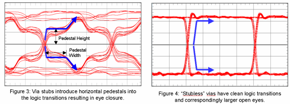
Figures 3 and 4 show representative eye-diagrams of two via structures, one with an intact stub and one without a stub.
Comparing Figures 3 and 4, one can see that via stubs introduce horizontal pedestals in the logic 0-to-1 and logic 1-to-0 transitions. These pedestals close the eye, making it more difficult for the digital receiver to ascertain whether the received signal is truly a logical one or a logical zero.
Source: Overview of Backdrilling - Sanmina:
Click image to view
See the link above for the full article.
More about stubs from Altera: High-Speed Board Layout Guidelines.
Daisy Chain Routing With Stubs
Daisy chain routing is a common practice in designing PCBs. One disadvantage of daisy chain routing is that stubs, or short traces, are usually necessary to connect devices to the main bus (see Figure 11–14). If a stub is too long, it will induce transmission line reflections and degrade signal quality.
Therefore, the stub length should not exceed the following conditions:
TDstub < (T10% to 90%) / 3
where TDstub = Electrical delay of the stub
T10% to 90% = Rise or fall time of signal edge
For a 1-ns rise-time edge, the stub length should be less than 0.5 inches
(see the “References” section). If your design uses multiple devices, all
stub lengths should be equal to minimize clock skew.
'via Blog this'
When designing high volume PCBs is important to consider the regional availability of the materials used in the stackup.

Reference: Understanding_The_PCB_Laminate_and_Prepreg_Process
CAF Resistant Requirements:
- Product
must pass 1000 hr CAF testing (100V, 85%RH, 85C).
- B
Stage (pre-preg) is restricted to the following glass styles: 106/1067,
1080/1086, 2113/3313 and 2116.
- C
Stage (cores) must have a resin content > 45%.
- Isola
370HR material is recommended for cost sensitive applications.
Notes: 7628 and 1652 glass should be avoided if CAF is a concern.
'via Blog this'